- This topic is empty.
-
AuthorPosts
-
2026-10-23 at 4:36 pm #30321
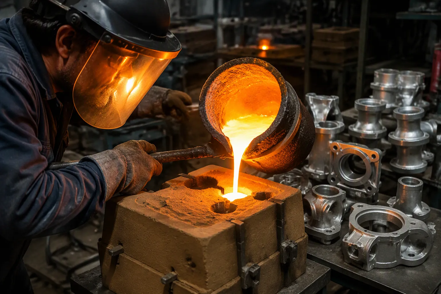
Image Source: https://www.xuxiangtaimetal.com Sand casting aluminum alloy components is a manufacturing process in which molten aluminum is poured into a cavity formed in a sand mold and allowed to solidify into a finished part. For B2B buyers in the US market, the sand casting process is often selected for its low tooling cost, design flexibility, and suitability for small-to-medium production volumes as well as large components. Key takeaways: alloy choice drives both properties and cost; tooling is inexpensive, but tolerances are wider than with other processes; design for manufacturability (DFM) and supplier quality control determine success.
Key Takeaways
- Choose the right aluminum alloy to balance strength, corrosion resistance, and cost for your part.
- Sand casting offers low-cost tooling but wider tolerances, so design parts with realistic tolerances and machining allowances.
- Apply design for manufacturability (DFM) principles and vet suppliers on quality control to avoid defects and ensure success.
What Is Sand Casting and How Does the Process Work?
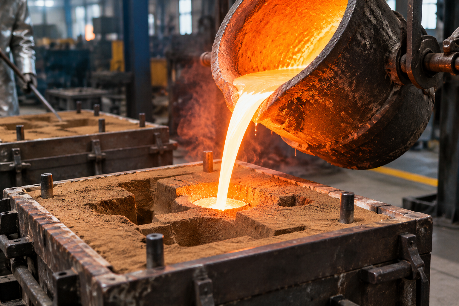
Sand casting remains one of the most versatile methods for producing aluminum alloy components. This section explains the sand casting process and identifies where it delivers the most value for buyers.
How the Process Works
The sand casting process begins with a pattern that replicates the final part geometry. Workers pack sand mixed with a binder around the pattern to form a mold cavity. They remove the pattern, pour molten aluminum into the cavity, and allow the metal to cool and solidify. The mold breaks apart during shakeout, and the raw casting proceeds to finishing operations.
Sand casting uses expendable molds, which introduces greater dimensional variability. Standard linear tolerances are therefore looser than those for permanent mold casting. Permanent mold achieves tighter tolerances and smoother as-cast surfaces because its rigid reusable mold reduces variability. The table below shows typical flatness tolerances for non-precision sand casting and precision sand or permanent mold.
Dimension range Flatness tolerance (non-precision sand) Flatness tolerance (permanent mold / precision sand) 0–6 in. 0.030 in. 0.020 in. Each additional 1–24 in. +0.003 in./in. +0.002 in./in. Over 24 in. Consult foundry Consult foundry Surface finish also varies by sand system. Conventional sand casting typically produces Ra values of 6.3 to 25 micrometers. Traditional green sand casting falls in the 12.5 to 25 micrometer range. Advanced resin-bonded sand systems achieve roughly 6.3 to 12.5 micrometers.
Sand Casting Condition Typical Ra (micrometers) Conventional sand casting (general) 6.3 – 25 Traditional green sand casting 12.5 – 25 Advanced resin-bonded sand systems ~6.3 – 12.5 Where Sand Casting Fits Best
Sand casting suits small-to-medium production volumes and large components with complex geometries. Buyers who need low tooling investment and design flexibility often choose this process. It also works well for parts with internal cavities and irregular curved surfaces. When tolerance and surface finish requirements are moderate, sand casting delivers a cost-effective solution.
Step-by-Step Sand Casting Process
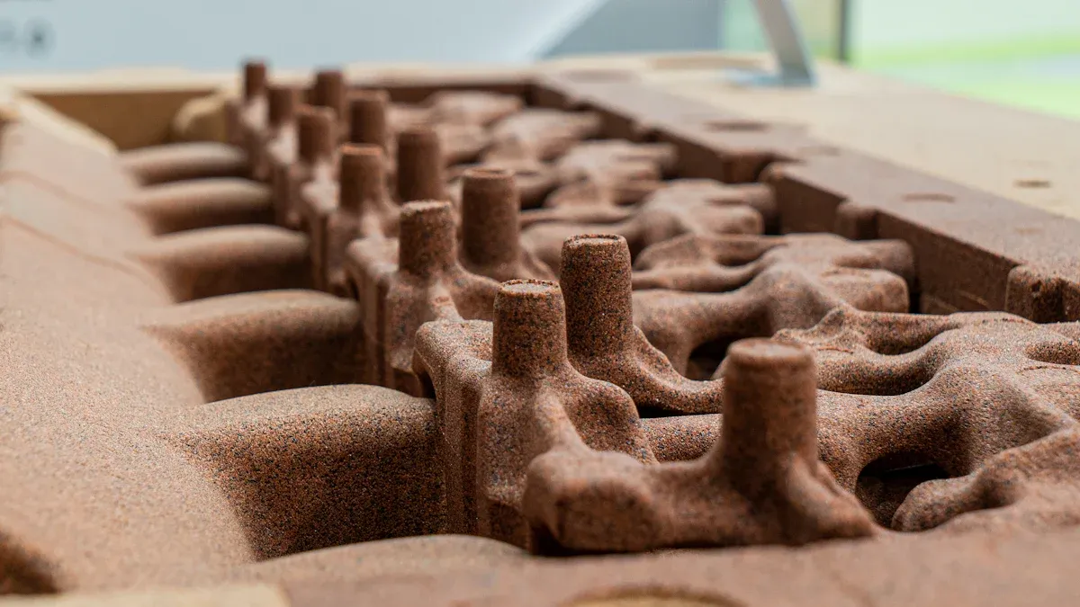
Image Source: https://www.xuxiangtaimetal.com A buyer who wants to write a professional English B2B knowledge article for the US market about sand casting aluminum alloy components should first understand the sequence of operations. Each stage affects cost, lead time, and final part quality.
Pattern and Mold Making
The process starts with a pattern, a physical master model oversized to account for aluminum’s roughly 1.3% shrinkage. Wood, plastic, and metal are common pattern materials. The choice depends on the expected usage quantity of the part. Workers pack refractory sand with a clay or chemical binder around the pattern. The mold splits into a cope (top) and a drag (bottom). Separate sand cores create internal passageways. Workers then remove the pattern, add gating channels, and apply a refractory coating.
Pouring, Cooling, and Shakeout
Operators melt alloy ingots, degas the melt, and flux it before pouring. Most aluminum alloys pour at 700–760°C (1300–1400°F). Thin, intricate parts need the higher end of this range for fluidity. Thick, simple shapes use the lower end to limit shrinkage porosity. Tilt pouring reduces turbulence and oxide formation. The metal then cools from the mold walls inward, and gating and risering feed the casting as it shrinks. After full solidification, a shakeout table vibrates the mold so the sand drops away for reuse.
Finishing and Inspection
Workers remove runners, gates, and risers, then grind and blast the surface to reach final dimensions. Inspection follows a defined sequence:
- Visual inspection catches cracks, flash, and surface inclusions.
- Dimensional inspection with calipers, micrometers, or CMMs verifies critical features against specified tolerances.
- Non-destructive testing such as radiography or liquid penetrant inspection detects internal porosity and voids.
- Mechanical testing confirms tensile strength and hardness.
Buyers who write a professional English B2B knowledge article for the US market about sand casting aluminum alloy components should note that inspection depth should match the application’s risk level.
Choosing the Right Aluminum Alloy
Alloy selection ranks among the most consequential decisions a buyer makes. The chosen grade sets mechanical properties, casting behavior, machining response, corrosion resistance, and final part cost. No single alloy serves every application. Buyers should match the alloy to the part’s service loads, environment, and finishing requirements.
Common Alloys Compared
Three alloy families dominate sand cast aluminum components: the Al-Si-Mg group (A356), the Al-Mg group (535.0), and the high-strength Al-Zn-Mg group (713.0). Each family offers a distinct balance of strength, ductility, and castability.
A356 is the workhorse of sand casting. It offers excellent fluidity, low shrinkage, and strong pressure tightness. A356 also responds well to heat treatment. Its mechanical properties depend heavily on temper and casting conditions.
Condition Ultimate Tensile Strength (MPa) Yield Strength 0.2% offset (MPa) Elongation in 50 mm (%) As-Cast (F) 165–207 83–124 3–5 T5 Temper 207–241 152–186 3–6 T6 Temper (Sand Cast) 234–310 165–234 3–10 T6 Temper (Permanent Mold) 276–345 207–276 5–12 In the as-cast condition, A356 delivers an ultimate tensile strength of 234 MPa (33,900 psi), a yield strength of 165 MPa (23,900 psi), and elongation of 3.5% in 50 mm. Its modulus of elasticity is 72.4 GPa, and Poisson’s ratio is 0.33.
A356-T6 typically delivers tensile strength in the range of about 33 to 45 ksi, yield strength of about 24 to 32 ksi, and elongation of roughly 3 to 12 percent. Where a part falls in those ranges depends mostly on the casting process, section thickness, and the quality of melt treatment.
535.0 is a magnesium-based alloy known for corrosion resistance in marine and saltwater environments. It offers good machinability and weldability. Its mechanical properties stay consistent across F and T5 tempers.
Property 535.0-T5 (Sand) 535.0-F (Sand) Tensile Strength (Ultimate) 35 ksi 35 ksi Tensile Strength (Yield) 18 ksi 18 ksi Elongation (% in 2 in.) 9.0 9.0 Hardness (BHN) 60–90 60–90 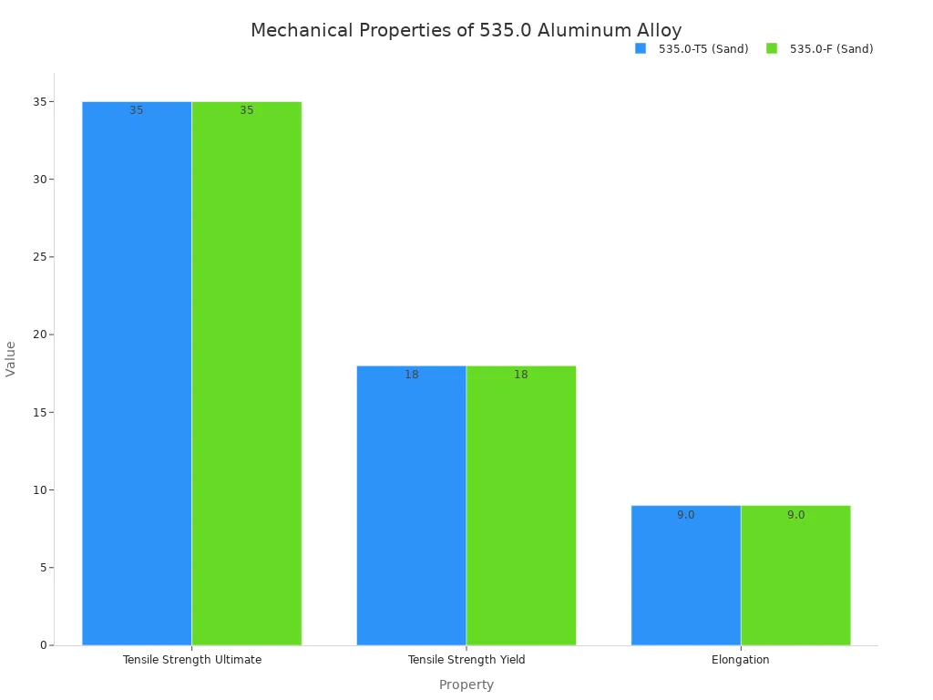
Image Source: https://www.xuxiangtaimetal.com 713.0 is a high-strength alloy that develops its properties through natural aging at room temperature. It reaches typical properties in 10–14 days, and a 21-day period is used for specification testing. Slight further strengthening continues up to about six months before the alloy stabilizes.
Property Value (MPa) Value (ksi) Tensile strength 210 30 Yield strength 150 22 Shear strength 180 26 Compressive yield strength 170 25 Elongation % 3 — The tensile, yield, and elongation properties of 713.0 are comparable to heat-treated alloys such as 355-T6 and 319-T6. Its impact strength exceeds those alloys, and elongation is often higher. The alloy shows strong resistance to impact and mechanical shock, absorbing sudden forces without easy cracking or deformation. This makes it suitable for vibration, sudden-load, and demanding environments.
Selection Criteria for Buyers
Buyers should evaluate candidate alloys against five practical criteria. The first is mechanical performance. A structural bracket under cyclic load needs higher yield strength than a decorative housing. A356-T6 or 713.0-T5 fits the first case, while as-cast A356 or 535.0 may serve the second.
The second criterion is the service environment. Parts exposed to saltwater, road spray, or chemical washdown benefit from the corrosion resistance of 535.0. Parts that face elevated temperatures need an alloy whose strength holds at operating temperature.
The third criterion is castability and part geometry. Thin walls and long flow paths demand high fluidity. A356 excels here. Complex internal cavities also favor A356 because of its low shrinkage tendency.
The fourth criterion is machining and finishing. Buyers who plan extensive CNC work should confirm the alloy’s machinability rating. Buyers who need anodizing should note that silicon content affects the cosmetic result. High-silicon alloys produce a darker, less uniform anodized finish.
The fifth criterion is cost and availability. Base metal price, melt loss, heat treatment cost, and scrap value all affect the delivered part price. A higher-strength alloy can reduce section thickness and part weight, which sometimes offsets its higher per-pound cost.
A practical selection sequence helps buyers avoid rework:
- Define the load case and required safety factor.
- Confirm the corrosion and temperature environment.
- Review wall thickness and geometry against alloy fluidity.
- Decide whether heat treatment is necessary or optional.
- Compare total landed cost across two or three candidate alloys.
Heat Treatment Options
Heat treatment unlocks the full potential of many sand cast aluminum alloys. The temper designation tells the buyer exactly which treatment the part has received. Buyers should specify the temper on every drawing and purchase order.
Temper Process Effect on Mechanical Properties F (As-Cast) No treatment Baseline strength, low ductility T5 Artificial aging after rapid cooling Increases yield strength, reduces residual stress T6 Solution heat treatment + quench + artificial aging Maximizes tensile strength and hardness The property gap between tempers is substantial. The table below shows representative values for a sand-cast alloy across the three common conditions.
Property As-Cast T5 T6 Tensile Strength (MPa) 310 345–360 Up to 380 Yield Strength (MPa) 130 160–175 190–210 Elongation (%) <1.5 2.0–3.0 3.5–4.5 Hardness (Brinell) ~80 ~90 ~100–105 T5 and T6 also differ in distortion risk and application fit. T5 relies on slower natural cooling, so quench-induced stress and distortion stay lower. T6 uses a rapid quench, which raises distortion tendency but delivers the highest strength and hardness.
Property T51 (T5-type) Temper T6 Temper Ultimate Tensile Strength 23 KSI (160 MPa) 34 KSI (235 MPa) Yield Strength 16 KSI (110 MPa) 24 KSI (165 MPa) Elongation N/A 3.5% Brinell Hardness 45–75 70–105 Distortion tendency Lower (slower natural cooling) Higher (quench-induced stress/distortion) Typical applications Non-structural (instrumentation, electronics, robotics) Structural (automotive, aerospace, defense, marine) T6 is more common with sand-cast alloys such as A356. T5 is typically used where full T6 response is limited or where dimensional stability matters more than peak strength. Buyers should discuss temper choice with the foundry early. Heat treatment adds cost, lead time, and a straightening step for thin sections. A foundry such as Qingdao Xuxiangtai Machinery Manufacturing Co., Ltd. can advise on temper selection for custom parts produced to buyer drawings, samples, and technical requirements.
Cost Analysis and Process Comparison
What Drives Sand Casting Costs
Several factors shape the final price of a sand-cast aluminum component. Pattern and mold cost sits at the low end, typically $500 to $3,000, with tooling lead times of one to two weeks. Metal cost follows part weight and alloy grade. Melting energy, labor, and yield loss add to the base price. Post-processing often carries the largest share for precision parts, because machining, heat treatment, and inspection each add time per unit. Buyers who write a professional English B2B knowledge article for the US market about sand casting aluminum alloy components should track these drivers closely, since they explain most quote-to-quote variation.
Sand Casting vs. Other Methods
Die casting demands high upfront tooling investment but yields the lowest per-part cost at scale, thanks to fast cycle times and minimal secondary machining. It suits mass production with stable demand. Sand casting offers the lowest tooling cost and fastest tooling turnaround, which suits prototypes, replacement parts, and low-volume runs. Investment casting tooling costs sit between the two, with moderate lead times. Its per-part cost exceeds die casting, but savings often come from reduced machining and assembly, especially for complex parts.
Factor Investment Casting Sand Casting Tooling cost $6,000–$30,000 $500–$3,000 Tooling lead time 4–12 weeks 1–2 weeks Best-fit volume Small to high volume Prototype to mid volume Sand casting’s cheap tooling gets offset by machining time on every single part, while investment casting’s higher tooling cost buys a near-net-shape part that needs little to no further work. For low volumes or very large parts, sand casting is usually cheaper overall.
Design for Manufacturability
Design for manufacturability (DFM) determines how smoothly a sand-cast aluminum part moves from drawing to production. Buyers who apply DFM principles early avoid costly pattern revisions, reduce scrap rates, and shorten lead times. This section covers the three design levers that matter most: wall thickness and draft angles, tolerances and machining allowance, and defect prevention.
Wall Thickness and Draft Angles
Wall thickness sets the foundation for a sound casting. Thin walls cool quickly and resist shrinkage porosity, but they demand high metal fluidity and careful gating. Thick walls cool slowly and tend to form shrinkage cavities at hot spots. A practical rule for aluminum sand casting keeps nominal walls between 3 mm and 6 mm (0.12 in. to 0.24 in.). Designers should avoid isolated thick sections and instead use gradual transitions. A uniform wall section feeds shrinkage evenly and produces more predictable mechanical properties.
Draft angles allow the pattern to release from the sand mold without tearing the cavity walls. Insufficient draft causes scuffing, mold damage, and dimensional error. The table below summarizes common draft angle guidance for sand casting patterns.
Guideline Draft Angle Rationale / Notes General thumb rule 1–2 degrees Considered a safe practice for typical sand casting patterns Generous / deep pockets 5 degrees Suggests very generous draft; needed for deep pockets, but adds casting weight and machining cost No universal standard Case-by-case No common industry standard exists; draft depends on pattern quality, molding method, machining allowances, sand type (green sand vs. no-bake/chemical-bound), pattern material (wood, urethane, metal), and foundry practices Buyers should treat these values as starting points. Deep pockets, rough pattern surfaces, and green sand molds push the draft angle toward the generous end. Smooth metal patterns and no-bake sand systems allow tighter draft. The foundry’s molding practice ultimately governs the final value, so buyers should confirm draft on the drawing review.
Tolerances and Machining Allowance
Sand casting produces wider tolerances than permanent mold or investment casting. Buyers who understand the tolerance framework can specify realistic requirements and avoid over-tightening the drawing. The ISO 8062 standard provides the common language for cast tolerances. Under this framework, cast tolerance grades (CT) scale with mold type and feature size. Sand processes typically land in CT9–CT11, while permanent mold casting can approach CT6–CT8 when metal dies control cooling more uniformly. For most structural greensand castings, ISO 8062 grades CT9–CT11 are specified for as-cast linear tolerances unless the feature is later machined to tighter tolerances.
Process ISO 8062 CT Grade Band Optimized aluminum sand casting CT9 – CT11 Standard green sand casting CT12 – CT14 Permanent mold / investment CT6 – CT8 The table below translates those grades into practical dimensional tolerances for common part sizes.
Casting Dimension (mm) Standard (CT9) Tight (CT8) Up to 100 ±1.5 mm ±1.0 mm 101 to 250 ±2.0 mm ±1.3 mm 251 to 400 ±2.5 mm ±1.5 mm 401 to 600 ±3.0 mm ±1.8 mm Machining allowance bridges the gap between as-cast tolerance and final part tolerance. A buyer who needs a bearing bore, a sealing face, or a mating surface should add stock to the casting and machine it afterward. Typical machining allowance for aluminum sand casting runs 1.5 mm to 3 mm (0.06 in. to 0.12 in.) per surface, depending on part size and feature criticality. Buyers should mark machined surfaces clearly on the drawing and specify the datum scheme. A clear datum scheme prevents tolerance stack-up errors during CNC setup.
Buyers should specify as-cast tolerances per ISO 8062 CT9–CT11 for general features and reserve tighter tolerances only for machined surfaces. Over-specifying as-cast tolerance raises cost without improving function.
Avoiding Common Casting Defects
Most casting defects trace back to design, gating, or process control. Buyers who recognize the defect patterns can raise the right questions during design review and supplier qualification. Porosity is the most common family of defects in aluminum sand casting. The table below lists the main porosity types and their causes.
Porosity Defect Cause Surface porosity Contaminates touching the exterior (dirt in drag half, dross from turbulent fill, improper mold coatings/sprays, oxides) Reaction porosity Metal reacts with sand cores, core binders, mold coatings, or sprays; always local and on the surface Gas hole porosity Trapped air from metal turbulence; rounded, localized holes Oxide inclusions Turbulence mixing with oxides in the molten aluminum; faster mold fill increases risk Shrinkage porosity Solidification defect; occurs at last-to-solidify regions, between thick/thin walls, or hot spots near the riser; appears elongated Hydrogen gas porosity Reaction between molten aluminum and hydrogen in the air; correlated with moisture and metal temperature (higher humidity/temperature = more hydrogen); appears throughout the casting, not localized A second group of defects relates to mold strength, core stability, and sand quality. The table below summarizes these causes.
Defect Cause Shrinkage Overheating, fast pouring speed, or excessive moisture in the sand mold Cracks from heat treatments Overheating or excessive stress from over-pulling the metal Casting cracks Develop along grain boundaries, more likely with specialty molds for complex shaping Dioxide slag Poorly designed pouring system, slag not removed from alloy liquid, or inadequate standing time after refining Stomata bubbles Poor ventilation of sand core/mold, impurities (grassroots, coal dust) mixed into sand, or poorly designed pouring system with inexact pouring speed A third group covers geometric and molding-related defects. Buyers should recognize these terms because they appear in inspection reports and corrective action requests.
- Blow – a large cavity/hole produced by gases that displace the molten metal.
- Scar – a shallow blow caused by improper permeability or venting, typically on a flat surface.
- Blister – a shallow blow like a scar but covered by a thin metal layer.
- Scab – occurs when part of the mold face lifts or breaks down and the recess is filled by metal; disengaged gas can break up sand that is washed away and filled with metal.
- Core shift – the core moves from its intended position due to buoyancy of the molten metal.
- Mold shift – the cope shifts sideways relative to the drag, leaving a step/indent at the parting line.
- Drop – an irregular projection caused by break-away of mold sand from weak packing, low molding-sand strength, equipment malfunction, or jolts/strikes at the flask during assembly.
- Penetration – a crust of fused sand where inadequate sand packing lets metal flow between sand particles into the mold wall.
- Buckle – a long, broad shallow depression across flat castings.
- Rat tail – a long, shallow, angular depression resembling a buckle but not broad-vee shaped.
- Pin holes – small gas holes at or just below the surface, occurring in large numbers and uniformly dispersed.
DFM reduces defect risk in several practical ways. Generous fillets at wall junctions spread shrinkage and lower hot-spot severity. Gradual section transitions prevent isolated heavy sections that feed shrinkage porosity. Well-placed risers and chills control solidification direction. Clean melt practice and proper degassing limit hydrogen pickup. Buyers who plan machining should also confirm that critical surfaces sit outside the last-to-solidify zones. A foundry such as Qingdao Xuxiangtai Machinery Manufacturing Co., Ltd. can review a drawing for these risks and recommend pattern, gating, and machining allowance adjustments for custom parts produced to buyer drawings, samples, and technical requirements.
Quality Control and Supplier Selection
Quality control protects the buyer from hidden defects and costly rework. A structured inspection plan confirms that each casting meets the drawing before it ships.
Key Inspection and Testing Methods
A capable foundry combines dimensional, material, and non-destructive checks. The table below summarizes the core methods and what each one verifies.
Test Method What It Verifies CMM, laser scanning, optical comparison Dimensional accuracy against the drawing Visual and roughness inspection Surface quality and visible flaws such as porosity or cold shuts Spectroscopic analysis (XRF, OES) Chemical composition of the alloy Hardness and tensile testing Heat treatment response and mechanical properties Radiography, ultrasonic, penetrant, eddy current Internal and surface-breaking defects Statistical process control monitors dimensional stability across a production run. Digital imaging and automated tools improve defect detection and reduce human error.
Questions to Ask a Supplier
Buyers should probe capability, not just price. Useful questions include:
- What casting tolerance can you actually hold, and can you show inspection data?
- Which inspections does the standard quote include?
- Can you supply a chemical composition report and mechanical test results per batch?
- Who designs the gating and risering system, and what happens if the first pour shows shrinkage?
- Do you run a qualified heat-treatment cycle with test bars from the same pour?
- What are your typical lead times for samples and production?
A supplier such as Qingdao Xuxiangtai Machinery Manufacturing Co., Ltd. supports custom manufacturing based on drawings, samples, and technical requirements, and can confirm inspection scope during quotation.
Buyers should confirm the process fits their volume and tolerance needs, select the alloy against mechanical and cost requirements, apply DFM principles early, and vet suppliers on QC capability. Early collaboration with the casting supplier reduces cost and lead time by consolidating finishing, testing, and logistics under one roof. Buyers can request a quote or DFM review with specific part requirements to start.
FAQ
When should a buyer choose sand casting over die casting?
Sand casting fits prototypes, low-to-medium volumes, and large parts. Die casting suits high-volume runs with stable demand. Tooling cost and volume decide the better fit.
What information should a buyer provide for an accurate quotation?
Buyers should send 2D drawings, a 3D model, alloy and temper, tolerance requirements, surface finish, machining scope, quantity, and delivery timeline. Qingdao Xuxiangtai Machinery Manufacturing Co., Ltd. quotes custom parts based on drawings, samples, and technical requirements.
What tolerances can sand casting realistically achieve?
Standard sand casting holds ISO 8062 CT9–CT11 for as-cast features. Machined surfaces reach tighter tolerances. Buyers should reserve tight tolerances for critical surfaces only.
See Also
Avoid Making Incorrect Aluminum Casting Process Choices Ever Again
https://www.xuxiangtaimetal.com
Qingdao Xuxiangtai Machinery -
AuthorPosts

- You must be logged in to reply to this topic.