- This topic is empty.
-
AuthorPosts
-
2026-10-15 at 1:45 pm #30169
A pull-cord switch must be positioned so that any person walking or working along the conveyor can reach the cord quickly, which makes switch spacing a site-safety decision driven by access routes, applicable safety rules and rope sag — not a fixed catalogue value. Belt-misalignment switches must be positioned where belt drift actually causes damage: at the head and tail pulleys, at transfer points and along sections where the belt leaves the normal track. KJT Sensors supplies both device families, including the KJT-LSTD pull-cord switch with manual or automatic reset, and states a typical spacing of 30–50 m per switch configured for the site. Final placement always requires a site risk assessment by a qualified conveyor or machine-safety engineer.
Key Takeaways
- Pull-cord switch spacing is a site decision: KJT Sensors’ product data for the KJT-LSTD gives a typical spacing of 30–50 m per switch, configured for the specific conveyor length, walkway layout and applicable safety standards.
- Reachability — not distance — is the core requirement: the cord must be graspable along the entire accessible conveyor length, on both sides where personnel work.
- Belt-misalignment switches observe the belt edge, and are concentrated at pulleys, transfer points and known drift zones; they issue warning and shutdown signals rather than emergency stops.
- Reset philosophy separates the two devices: a manual-reset pull-cord switch latches until an operator confirms the emergency is cleared; misalignment switches commonly use automatic or field-verified reset for condition monitoring.
- Every spacing value, mounting height and trip-angle setting in a real project must be confirmed against the site risk assessment and applicable local safety regulations.
Why Positioning Decides Whether These Switches Work
Both device families fail in the same way when positioned badly: a pull-cord switch that is too far from a walkway cannot be reached in an emergency, and a misalignment switch mounted where the belt never drifts detects nothing. Positioning is therefore an engineering task, not an accessory choice.
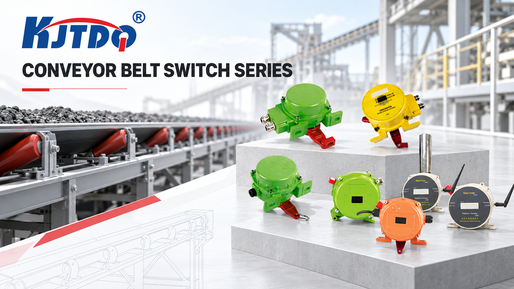
KJT Sensors positions these products as part of a complete conveyor protection portfolio — pull-cord switches, belt misalignment switches, two-way pull-cord switches, slip detection devices, plugged-chute switches, longitudinal tear detectors, material level/flow switches and audible and visual alarms — configured around conveyor length, belt width, speed, material and control-system interfaces (manufacturer-stated, Conveyor Belt Switch Series).
The system-level view — which devices a conveyor needs at all — is covered in the conveyor belt protection system guide. This article covers only the positioning of the two line-side families.
Pull-Cord Emergency-Stop Switches: What Positioning Must Achieve
The function that constrains placement
A pull-cord switch provides emergency-stop protection along the conveyor line. Steel wire ropes installed along the conveyor sides can be pulled at any point to actuate the switch, interrupt the conveyor control circuit and stop the system (manufacturer-stated, KJT-LSTD product data). Placement must therefore guarantee:
- Continuous reachability — no accessible point on the conveyor should be more than a short step from the cord.
- Both sides where personnel work — walkways on both sides require cord coverage on both sides.
- Unobstructed cord run — the rope must run without snagging on structure, idlers or material chutes.
- Reset access — a manual-reset model must be reachable by the responding operator, because the conveyor cannot restart until the reset button is pressed.
What actually determines spacing
Input Effect on pull-cord switch placement Conveyor length and access-route layout Longer conveyors need more switches so the cord run stays taut and reachable; the number of installation points is configured to the site Walkway position (one side or both) Determines whether one or two cord runs — and correspondingly more switches — are required Applicable site safety rules and standards Site and national conveyor safety regulations can fix maximum distances or require additional stop points; these override catalogue guidance Rope sag and switch type Longer spans between switches increase rope sag; the site configuration balances span, rope tension and switch actuation force Explosion-proof or corrosive areas Standard products are not for hazardous areas; certified configurations change the available models and mounting KJT Sensors’ KJT-LSTD product data states installation spacing is configured for the site, with a typical spacing of 30–50 m per switch, and that conveyors of 800 mm, 1,000 mm, 1,200 mm width and above can be accommodated (manufacturer-stated). This typical range is a starting point for layout, not a substitute for the site risk assessment.
Reset choice interacts with placement
The KJT-LSTD family is available in manual-reset and automatic-reset versions. Manual reset suits conveyors with stringent safety requirements where inadvertent restart must be prevented: after actuation, an operator must physically press the reset button before operation resumes. Automatic reset suits temporary warning applications that do not require strict latching (manufacturer-stated). If a manual-reset switch is mounted where the reset button is hard to reach, the safety benefit of latching is offset by slow recovery — so reset access belongs in the placement plan, not just the specification.
Wiring positions declared at layout time
The KJT-LSTD uses a normally closed contact for the emergency-stop circuit and a normally open contact for PLC, audible/visual alarm or remote-alarm connection (manufacturer-stated). Planning the switch positions together with the control-cabinet interface avoids re-pulling cable after the layout is fixed — the belt conveyor protection selection guidance recommends confirming control-system interfaces, contact configuration and wiring method before ordering (conveyor belt protection system guide).
Belt-Misalignment Switches: What Positioning Must Achieve
The function that constrains placement
A belt-misalignment switch monitors lateral belt deviation — whether the belt is leaving its normal track — to reduce the risk of belt damage and structural contact before it escalates. Unlike a pull-cord switch, it is a condition-monitoring device: it acts on the belt’s position, not on a human emergency. Placement is therefore governed by where belt drift causes damage, not by human reach.
Where misalignment switches observe the belt
Location Why it is monitored Head pulley approach Drift at the head pulley risks belt-edge damage and material spillage at the discharge Tail pulley and loading zone Belt loading forces and pulley alignment errors initiate drift here Transfer points and chutes Impact loading and off-centre feeding push the belt sideways Long intervening sections Intermediate switches catch drift that develops between the pulleys, at intervals set by the site layout Known drift zones from operating history Sections with recurring drift deserve explicit coverage Misalignment switches are typically installed in pairs on both sides of the belt at each monitored cross-section, with the roller or detection arm set at a defined distance and angle from the normal belt edge. The exact trip angle, edge clearance and mounting height are model- and site-specific, and must be confirmed for the specific switch model and the belt’s geometry — this article deliberately states no universal trip-angle value because none can be validly generalized.
Warning and shutdown contacts
Misalignment protection is commonly staged: an early warning contact signals developing drift for operator attention, and a shutdown contact trips the conveyor when deviation exceeds the limit. The KJT Sensors belt conveyor protection portfolio includes misalignment monitoring as part of an integrated protection scheme together with slip, blockage, tear and material-flow detection (manufacturer-stated, Conveyor Belt Switch Series). Confirming which contact stages a specific model provides belongs to model selection, which is covered with the other condition switches in the conveyor condition-switch selection guide.
Pull-Cord Switch vs Belt-Misalignment Switch: Placement Compared
Placement dimension Pull-cord switch Belt-misalignment switch Primary decision driver Human reachability along the conveyor Where belt drift causes damage Typical mounting reference Line-side, along walkways, both sides where worked Both sides of the belt at pulleys, transfers and drift zones Spacing basis Site-configured; typical 30–50 m per switch (manufacturer-stated, KJT-LSTD) Set by monitored cross-sections, not by a fixed span Reset philosophy Manual reset latches for strict safety requirements; automatic reset for warnings Condition monitoring; staged warning/shutdown logic Circuit role Emergency-stop circuit (normally closed contact) Condition warning and interlock (PLC/alarm contacts) Regulatory basis Site and national conveyor safety rules apply directly Machine protection logic; set with the control scheme Which Placement Decisions Require a Site Risk Assessment
The following decisions must not be taken from generic guidance alone:
- Final switch spacing and count — derived from conveyor length, walkway layout, applicable safety standards and the site risk assessment.
- Cord coverage on both sides — determined by where personnel actually work, verified on site.
- Manual vs automatic reset selection — a safety-procedure decision, not a convenience preference.
- Misalignment trip limits — trip angle and edge clearance interact with belt width, speed and structure; wrong settings produce either nuisance trips or missed drift.
- Hazardous-area installations — standard products must not be used in explosion-hazardous areas; certified configurations are required, and the applicable area classification is a site determination.
- Emergency-stop circuit integration — how the normally closed stop contact and normally open alarm contact land in the control scheme must be reviewed by the conveyor controls engineer.
A placement plan prepared from this article should be treated as input to that review, not as its replacement.
KJT Sensors Options for These Applications
KJT Sensors’ conveyor belt switch series includes dedicated product families for both functions discussed here:
- Pull-cord switches, including two-way pull-cord switches: line-side emergency stop with manual or automatic reset, IP65/IP67 options, adapted to dust, moisture, vibration and light-corrosion environments; explosion-proof, anti-corrosion and high/low-temperature configurations can be discussed for special operating conditions (manufacturer-stated, KJT-LSTD product data).
- Belt-misalignment switches: lateral-deviation monitoring within the integrated conveyor protection portfolio, configured with the slip, tear, blockage, material-flow and alarm devices around conveyor length, belt speed, material type and control-system interfaces (manufacturer-stated).
Sensing distance, contact configuration, IP rating and mounting method must be confirmed for the specific model. Pricing is quoted by model and project requirements, based on switch type, reset method, IP rating, number of installation points and whether a complete protection set is engineered for the conveyor.
What to Send With a Positioning Review Request
To make a placement review productive, KJT Sensors’ selection guidance recommends providing:
- conveyor layout drawing or site photographs, including walkways;
- conveyor length, belt width and belt speed;
- conveyed material and environment (dust, moisture, corrosion, temperature);
- where personnel work along the line, and on which side(s);
- control-cabinet interface: normally open / normally closed contact usage, PLC or alarm integration;
- applicable site safety rules and any hazardous-area classification;
- existing equipment models when extending or replacing an installed system.
The same application-information discipline applies to every sensor selection — the complete checklist is covered in the sensor application information guide.
Limitations and Validation Needs
- The 30–50 m typical spacing is a manufacturer-stated starting value for the KJT-LSTD family; it is not a safety-standard distance and must not be used as one.
- No trip-angle, edge-clearance or mounting-height value is given for misalignment switches in this article because these are model- and belt-geometry-specific; they require confirmation for the specific switch model and site.
- This article does not replace a site risk assessment, a conveyor safety standard, or review by a qualified conveyor or machine-safety engineer.
- Standard products are not certified for explosion-hazardous areas; certified configurations and area classification are site decisions.
- All device statements are manufacturer-stated (Grade B evidence); model-level datasheets and certificates apply at ordering.
FAQs
Does a pull-cord switch need its own power supply? No. The KJT-LSTD is a mechanically actuated device — pulling the rope changes the contact state through the cam mechanism, with no additional power supply required. The contacts are wired into the control circuit or PLC/alarm system (manufacturer-stated).
Is the 30–50 m spacing a standard I can design to? No. It is a manufacturer-stated typical value for layout planning, configured for the site. The final spacing must come from the site risk assessment, walkway layout and applicable conveyor safety regulations, which take precedence over any catalogue value.
Where exactly should belt-misalignment switches be mounted? At cross-sections where drift causes damage: head and tail pulley approaches, transfer points and loading zones, plus intervening sections per the site layout — typically in pairs on both sides of the belt, with trip limits set for the specific belt geometry. The exact positions require the site review described above.
Why choose manual reset instead of automatic reset for a pull-cord switch? Manual reset latches after actuation so the conveyor cannot restart until an operator has confirmed the emergency is cleared — suitable where stringent safety requirements apply. Automatic reset suits temporary warning duties that do not require latching (manufacturer-stated).
Can these switches be used in a dusty or outdoor environment? The KJT-LSTD offers optional IP65/IP67 ratings for dust, moisture, vibration and light corrosion; explosion-proof, anti-corrosion and high/low-temperature configurations can be discussed for special conditions. The applicable configuration must be confirmed for the actual environment.
Where do slip, tear and plugged-chute switches fit relative to these two? They are condition-monitoring devices for different failure modes — slip, longitudinal tear and chute blockage — and are selected and positioned by their own logic, covered in the conveyor condition-switch selection guide within the overall protection system (conveyor belt protection system guide).
Conclusion
Positioning pull-cord and belt-misalignment switches is where a conveyor protection design either works or quietly fails. Pull-cord placement follows people — continuous reachability along every accessible point, both sides where worked, reset access, and spacing that comes from the site risk assessment rather than a fixed rule, with 30–50 m per switch as a manufacturer-stated typical starting value. Misalignment-switch placement follows the belt — pulleys, transfers and drift zones, with trip limits set for the specific geometry. Neither decision should be finalized without a qualified conveyor or machine-safety engineer reviewing the plan against the applicable site standards.
Sources
- KJT Sensors, Conveyor Belt Switch Series (category page, verified accessible 2026-10-10): https://www.kjt-sensors.com/list-conveyor_belt_switch_series.html
- KJT Sensors, KJT-LSTD Conveyor Pull-Cord Switch product data (internal knowledge base, Grade B manufacturer-stated)
- KJT Sensors, Belt Conveyor Protection Products selection guidance (internal knowledge base, Grade B manufacturer-stated)
- KJT Sensors, Solutions (verified accessible 2026-10-10): https://www.kjt-sensors.com/list-solutions.html
https://www.kjt-sensors.com/
KJT Sensors -
AuthorPosts

- You must be logged in to reply to this topic.